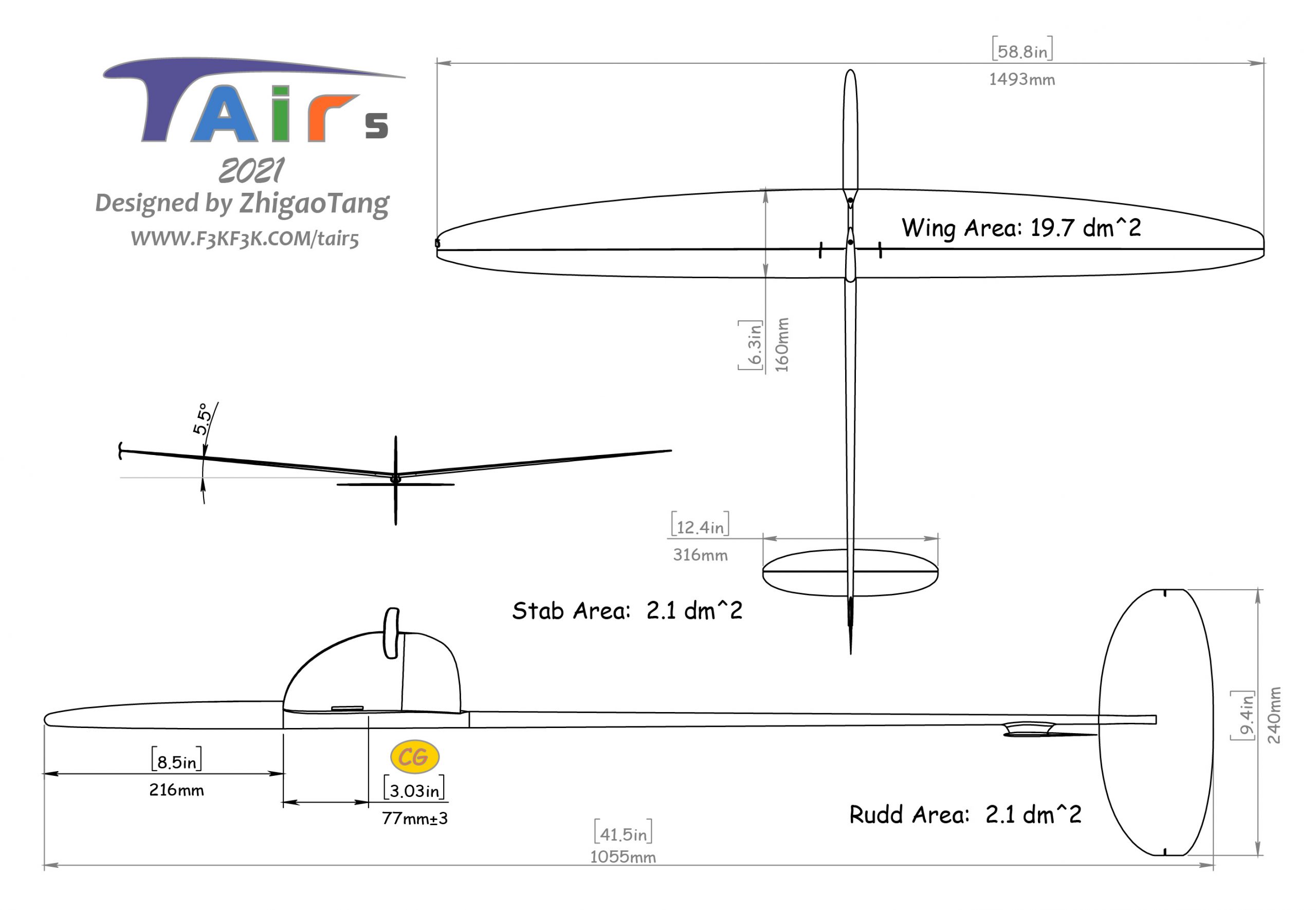
2021 TAIR5 F3K GLIDER
$780
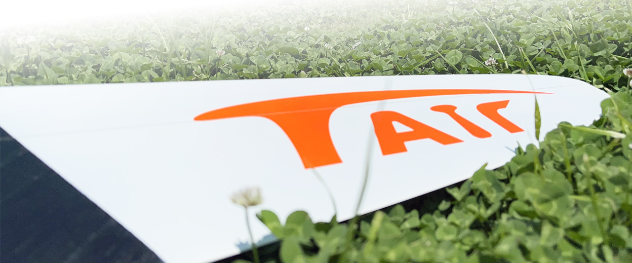
TAIR5 introduction
The design principle of the Tair 5 Discus Launch Glider is to make the glider higher, stronger, and newer.
Aerodynamically, we adopted a more extreme design of fuselage, so that the drag produced by fuselage is extremely small. In this case, most DLG pilots can easily launch it to more than 210 feet. The airfoil of Tair5 has been optimized with 10 years’ effort. The performance in thermaling, light-thermal climbing, and penetartion achieves a new mile-stone.
Structually, to obtain a higher strength of fuselage and wings, the manufacutrer of Tair uses the high-modulus carbon fabric with top quality, high-temperature carbon fabric molding technique, and specifically optimized multi-spar wing strucutre. Moreover, the arrangement of servos and ballast mount inside the fuselage is also a novel design.
A brand new design of ballast system enables pilots to quickly adjust the CG of the Tair5 based on different conditions in a contest.
Before you start:
It’s quite challenging to build a composite gliders.If you did not have any experience building a composite glider before, then we encourage you to purchase a Ready-To-Fly (RTF) version of the Tair5 or a used one, which will help you determine the key to succesfully build this glider, because it is very important and necessary to have a proper weight of your glider after everything is installed. If you are ready to build a perfect glider by yourself, then let’s get started.
Assembly Steps
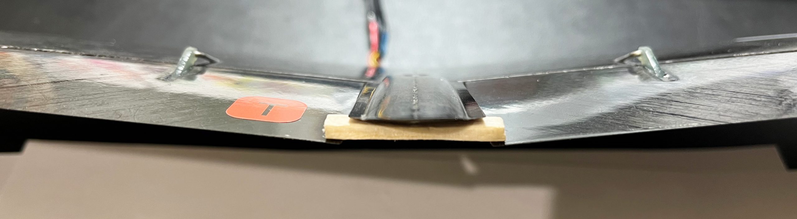
Step1:Launch peg installation
Step2:Flapron (Top-Driver) installation
Step3:Tail Installation
Step4:Fuselage Installation
Step5:Programming and testing
Step1:Launch peg installation
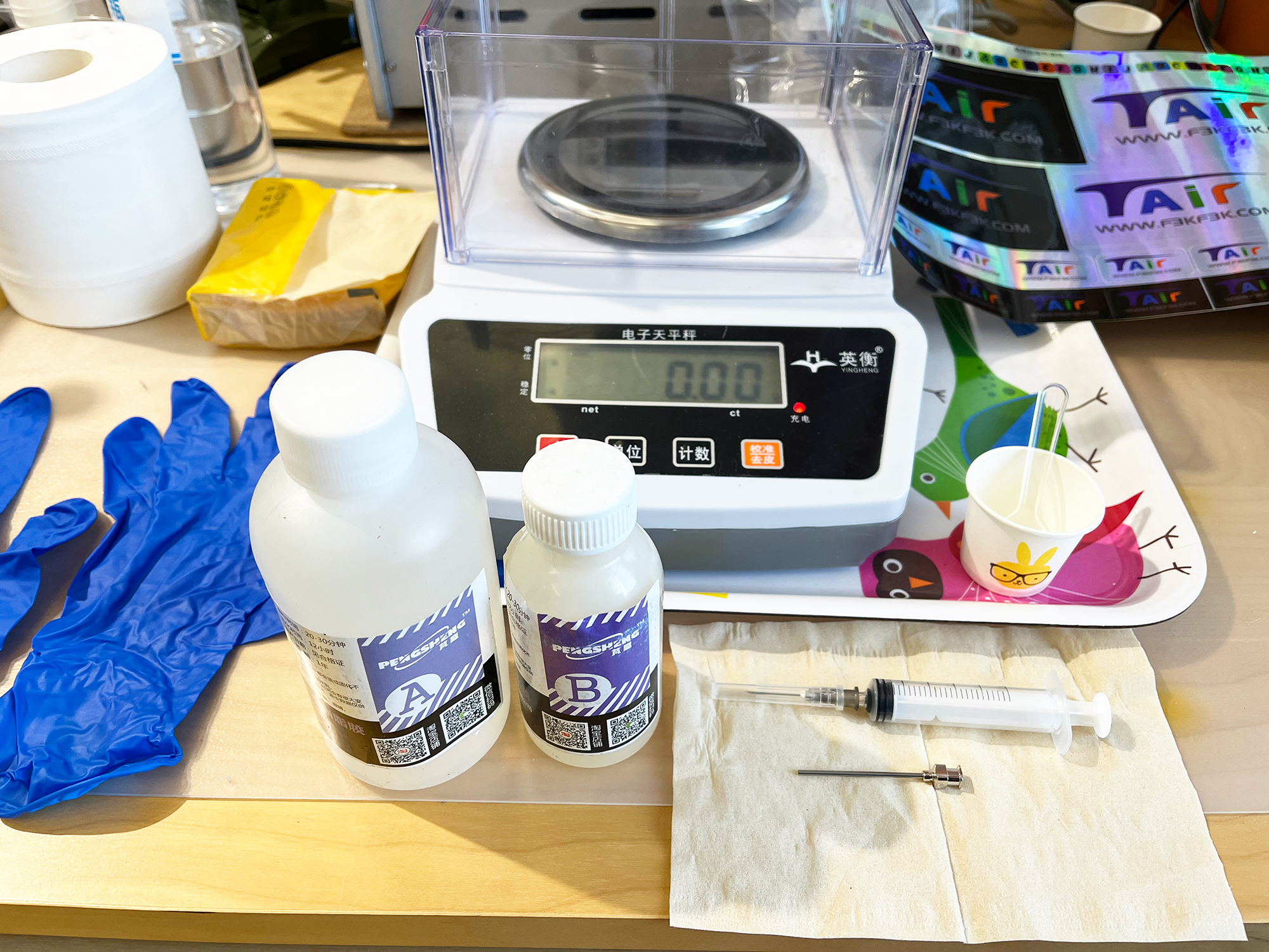
Consumables needed:Masking Tape(3M2090), Epoxy Resin(E51 with medium viscosity), small disposable plastic cup, stir stick,disposable syringe and needles, disposable Nitrile gloves;
Tools needed:Balance(500g, 0.1g), ruler, blades, files, dremel, drill, PE cover (not sticky), vacuum cleaner;
Tips:To have proper tools is also a important step. Please purchase as needed.
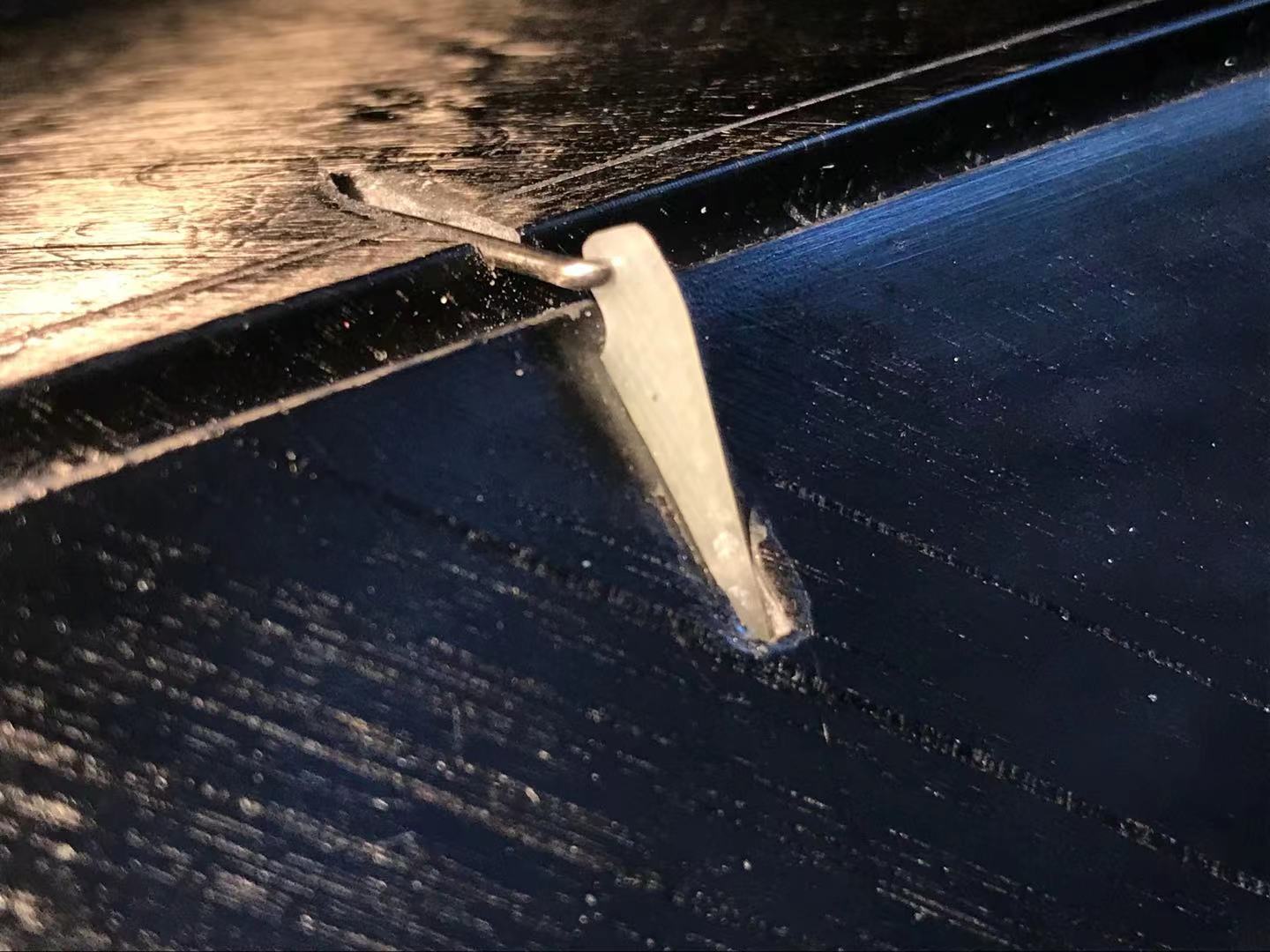
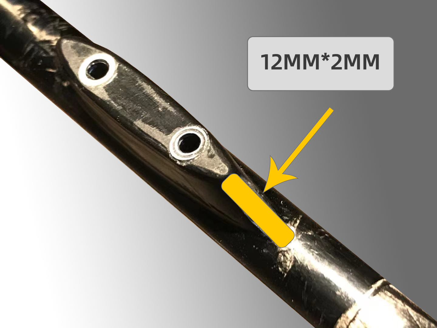
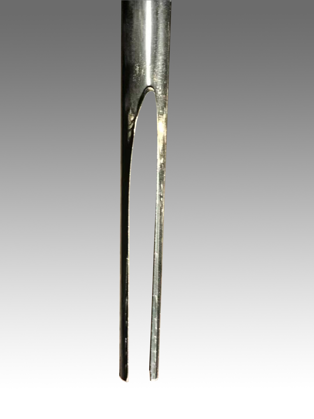
A:Use masking tape to cover the wing tip. Label the part that you need to cut for T-peg installation, and cut it with a blade or a dremel.
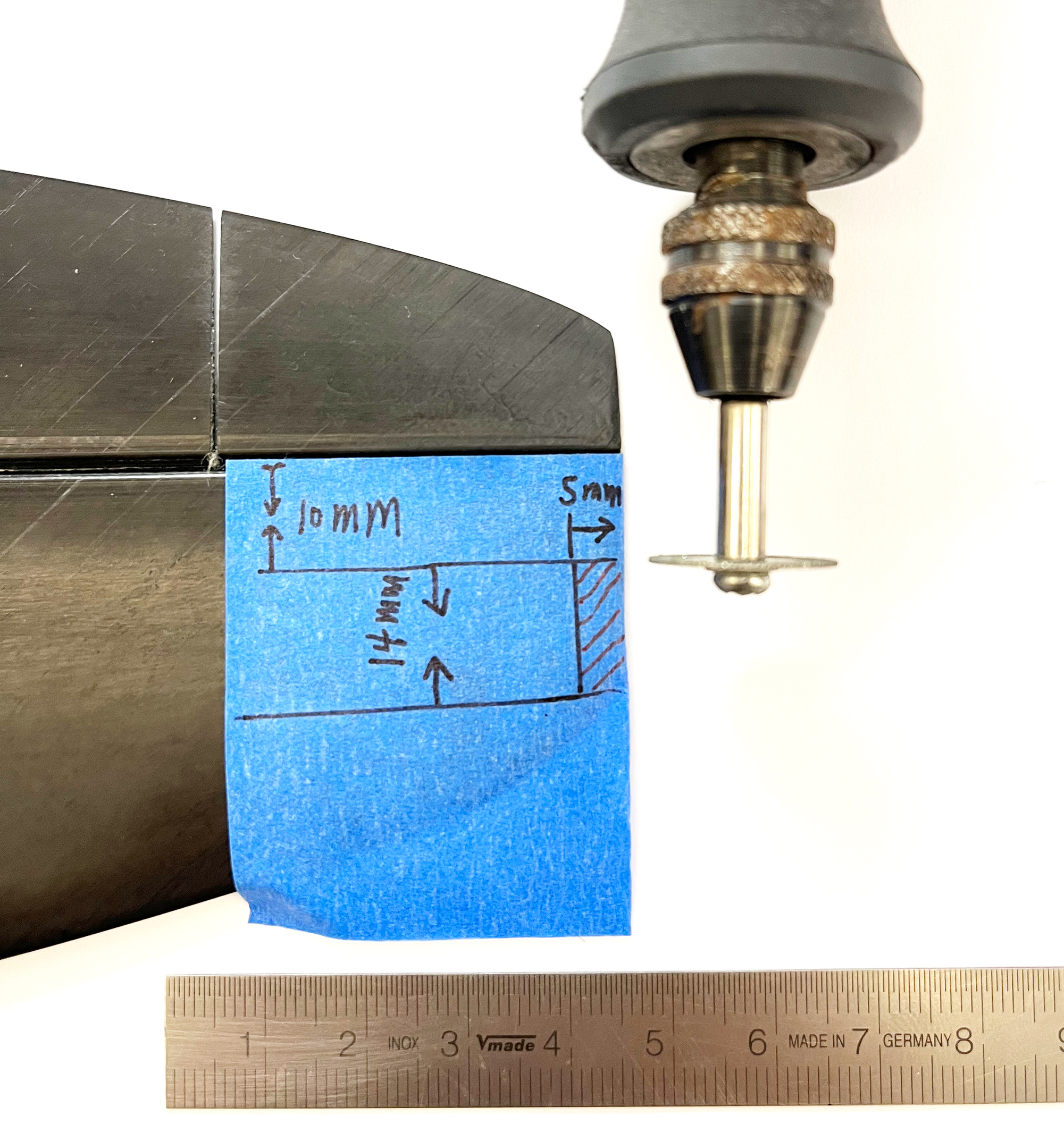
B:Remove the foam at where you are gonna install the T-peg using a blade or a dremel to provide enough space for the arm of the T-peg;
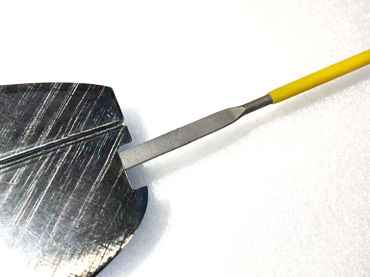
C:Clean the slot on the wing you cut for the T-peg and sand the arm of the T-peg with a file;
D:Mix the Epoxy Resin with the correct ratio in a container. Stir, and pour it into the syringe. Inject the epoxy to the slot and then insert the sanded T-peg.
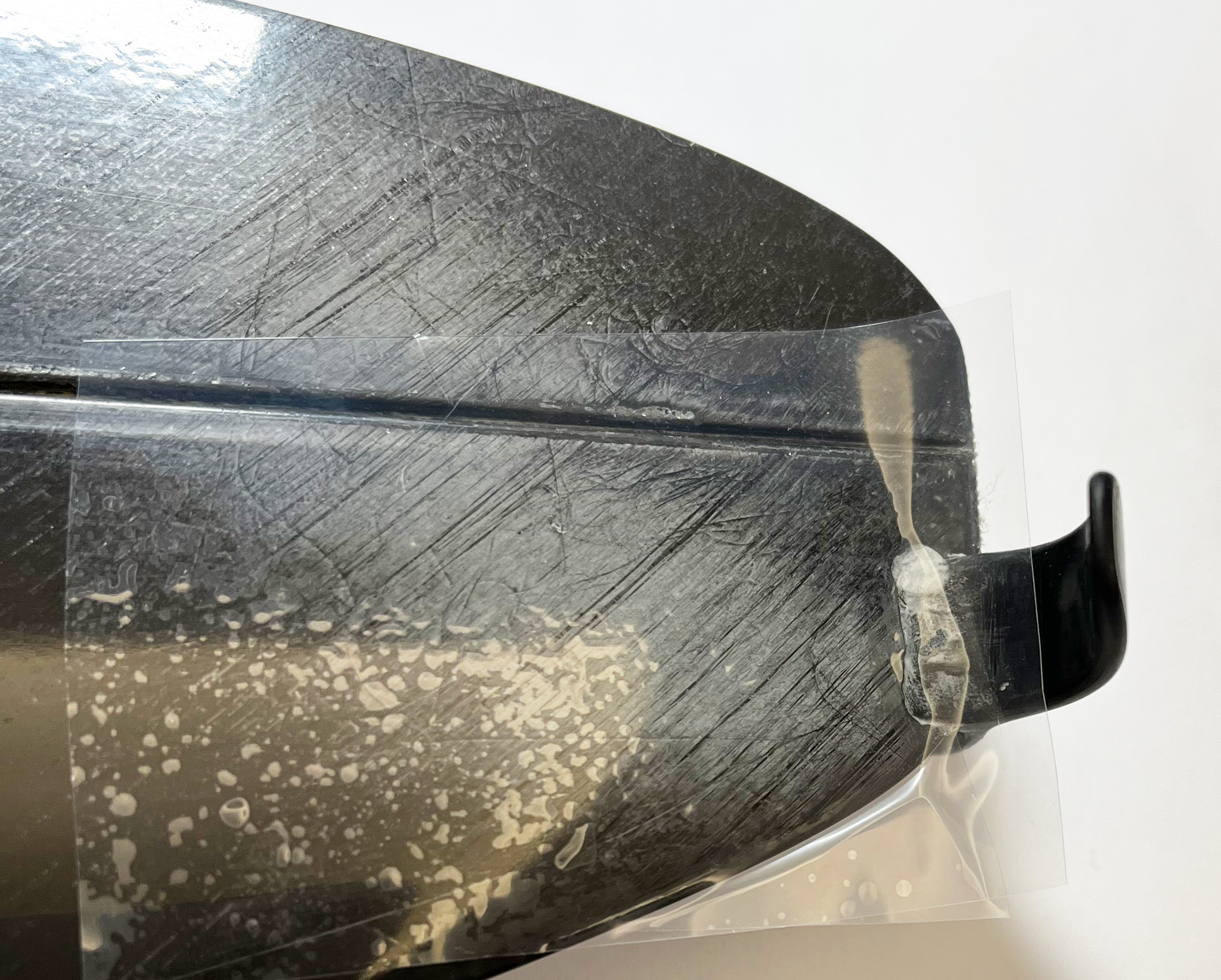
E:Wipe the extra Epoxy away after inserting the T-peg into the slot. Put a PE cover on both side of the wing, and clamp it with a stainless steel ruler (or something similar) for 12 hours until the epoxy gets hardened.
Step2:Aileron (Top-Driver) Installation
Consumables needed:Masking Tape(3M2090), Epoxy Resin(E51 with medium viscosity), small disposable plastic cup, stir stick,disposable syringe and needles, disposable Nitrile gloves
Tools needed:Balance(500g, 0.1g), ruler, blades, files, dremel, drill, PE cover (not sticky), vacuum cleaner
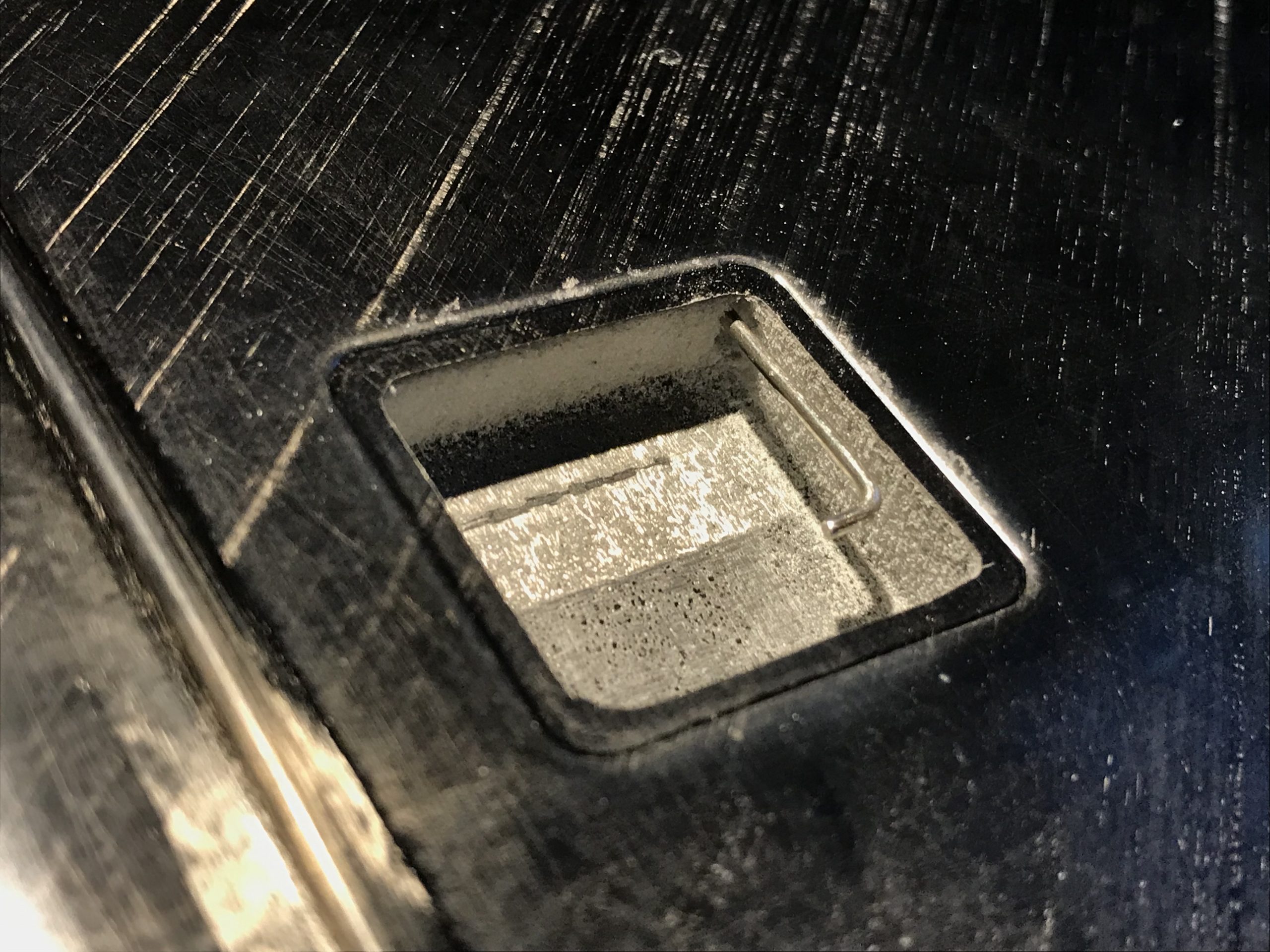
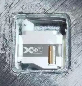
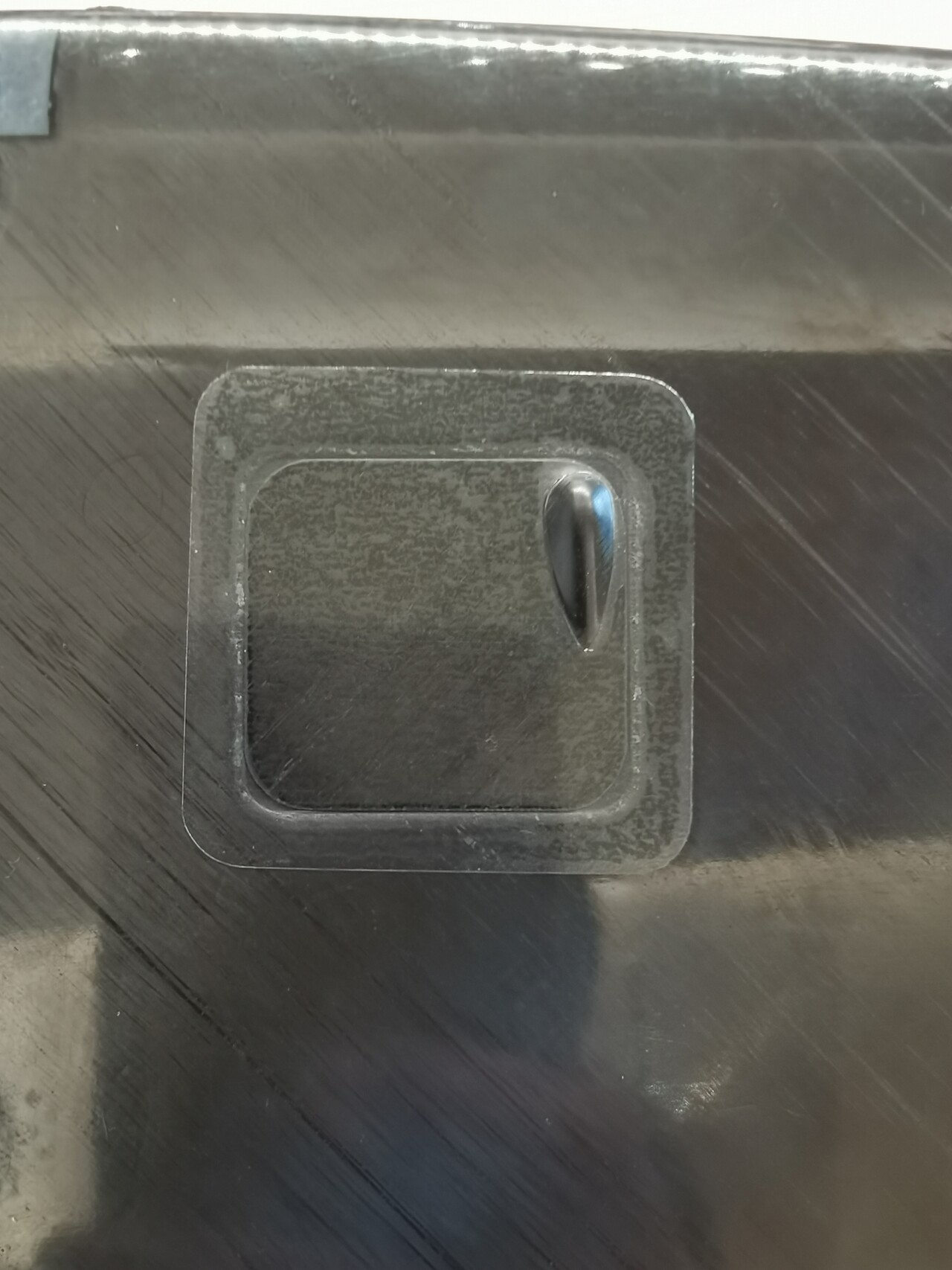
A:Cut the desinated space for servos on the wing with a blade. Remember to leave ~1mm on each side of the TD servo square. Remove the PMI foam core at the square you cut using a twizzer or a file.
B:Use a drill of 1.2mm diameter to drill a hole for the pushrod. Cut the extra part of the servo arm that you don’t need using a plier, and sand it to make it look nicer.
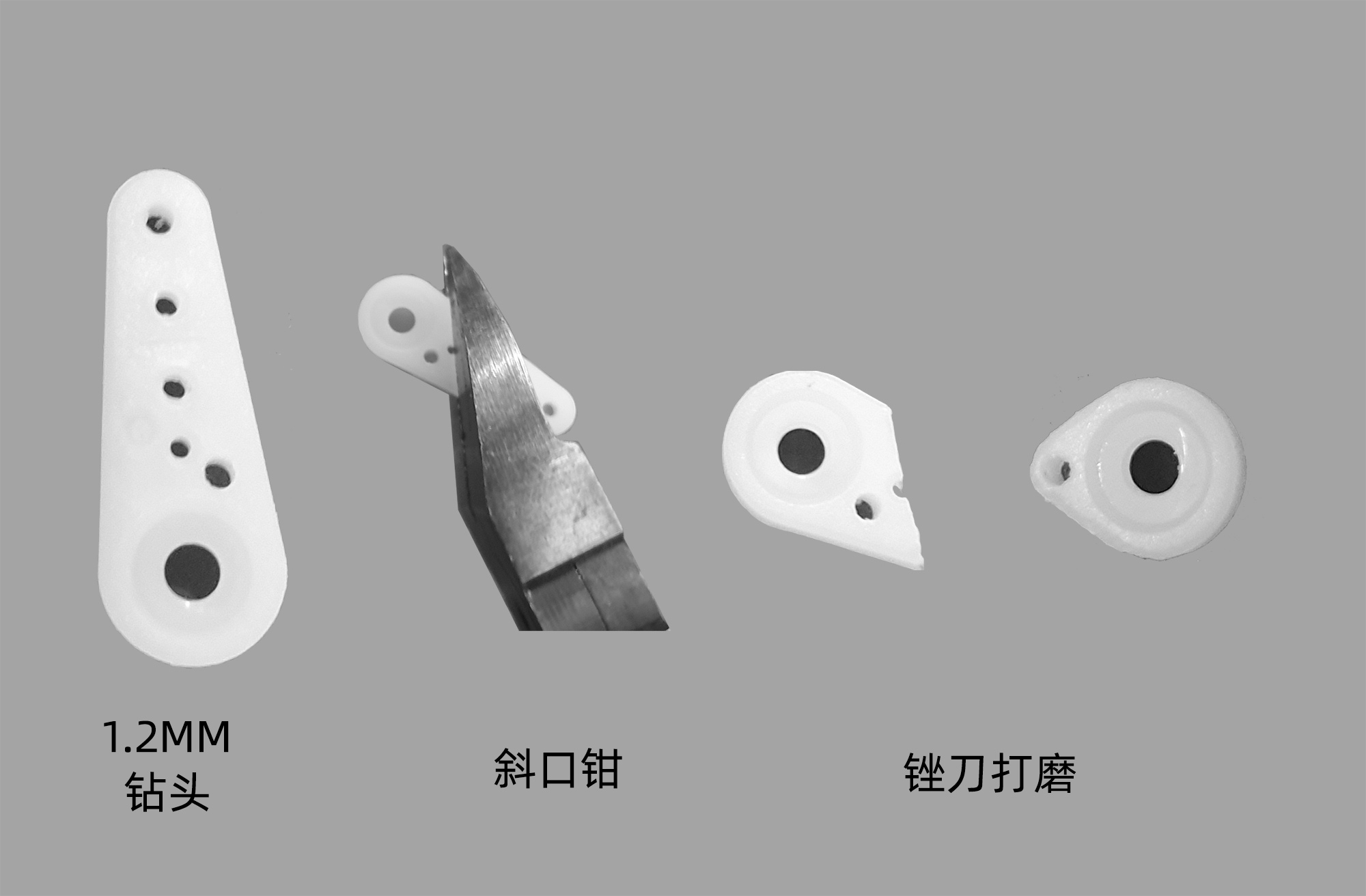
C:Put the TD horn at the designated position, and glue it with Epoxy (or CA).
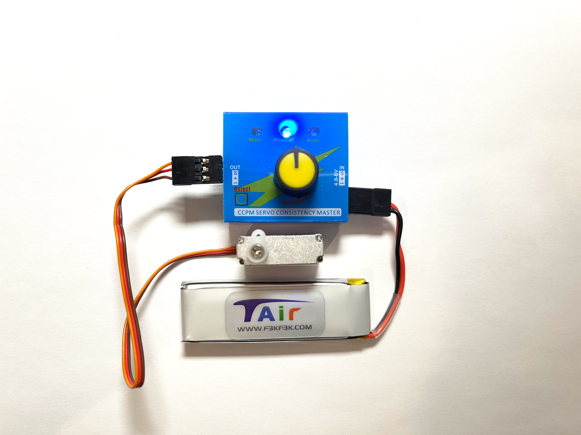
D:Make sure to adjust the servos for aileron to neutral position using your transmitter and the receiver you’ll use for this DLG.
E:Drill a hole that connect the TD servo square and the central front part of the wings for wires and pin.
F:Schematic figure: please figure out the negative and the positve. NOTE; you can also use your own pin or other ways you feel comfortable to connect the TD servos to your receiver
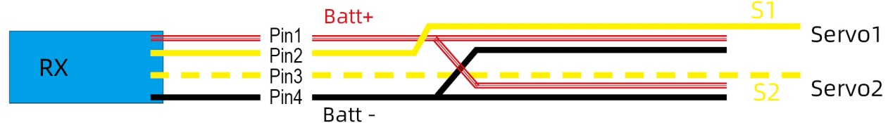
The precision of flapron control will directly affect the performance of your DLG. Whether it’s precise or not is determined by the quality of servo, the stiffness of the pushrod, and the gap between the pushrod and the horn (and the servo arm). The poor precision will lead to double-neutral.
The flaprons of Tair5 are dirven by TD (Top Driver). This structure will give you the best aileron control precision.
To ensure the performance of the Tair5, we recommend the following servos with priority listed. Note: 2 servos for the wings in total.
D5701
FRSKY- 6.5g
- (3.6-5V)
- Thickness 6mm
- Flat cover
- SBUS
- Programmable
X06
KST- 6.4g
- 2S(7.2-8.4V)
- Thickness 7mm
- Flat cover
- no SBUS
- no Programmable
A08N
KST- 8.3g
- 1s/2s(3.6-8.4V)
- Thickness 8mm
- cover with a ridge
- no SBUS
- Programmable
AG300
FUTABA- 11.4g
- 1S/2S(3.6-8.4V)
- Thickness 8mm
- cover with a ridge
- SBUS
- Programmable
低于7mm厚度的舵机在Tair5副翼上可以用平盖减少阻力
8mm厚度的舵机需要打磨0.3mm才能装在在Tair5副翼上,并且需要使用凸盖
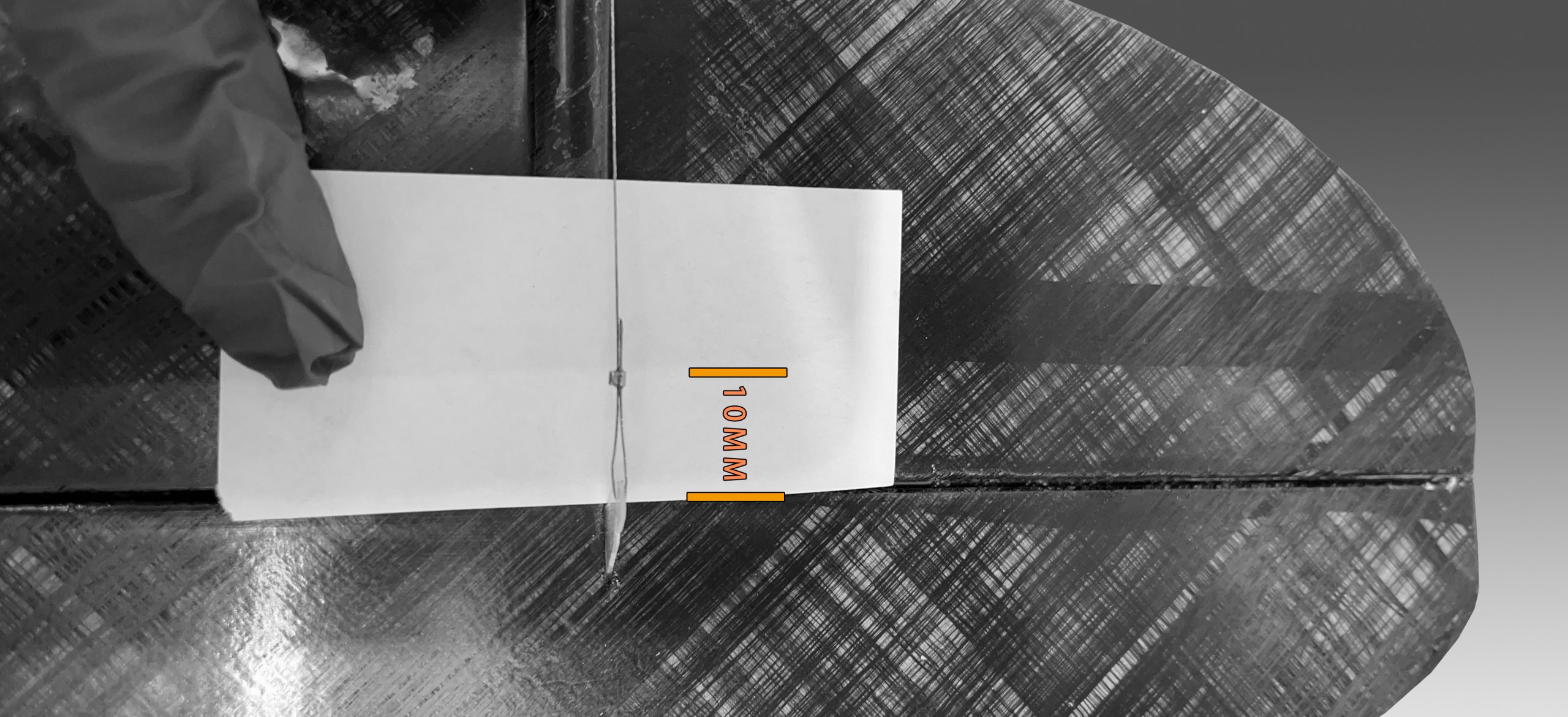
When the servos are at the neutral postion, you should have 3mm down flapron camber, so that you will have enough throw for the flapron air brake. Then, glue the servos using epxoy or CA.
Step3:Tail Installation
Consumables needed:Masking Tape(3M2090), Epoxy Resin(E51 with medium viscosity), small disposable plastic cup, stir stick,disposable syringe and needles, disposable Nitrile gloves
Tools needed:Balance(500g, 0.1g), ruler, blades, files, dremel, drill, PE cover (not sticky), vacuum cleaner
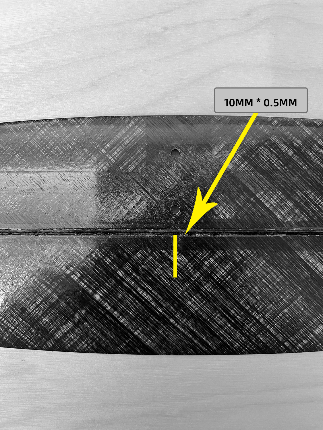
A:Cut a slot on the back of the horizontal stab mount for the elevator horn using a dremel, and sand it with a file.
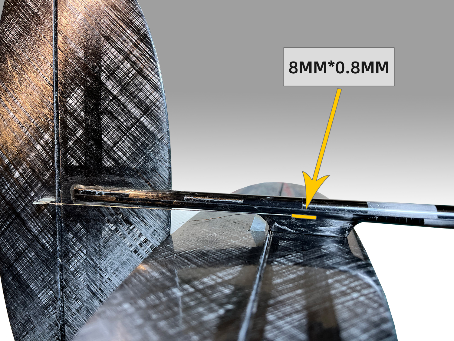
B:Cut a slot on the tail where you are supposed to insert the vertical fin using a dremel. Sand it with a file;
C:用刀切出水平尾翼舵角槽,插入舵角;用刀切出垂直尾翼舵角槽,插入舵角;
D1:用电摩砂轮切割出垂直尾翼出线孔
D2:水平尾翼装进机身后,确认转动无干涉,然后使用495
固定舵角,如左图;
D3:垂直尾翼插进图B的槽内,用环氧树脂固定,注意垂直于机翼水平面;
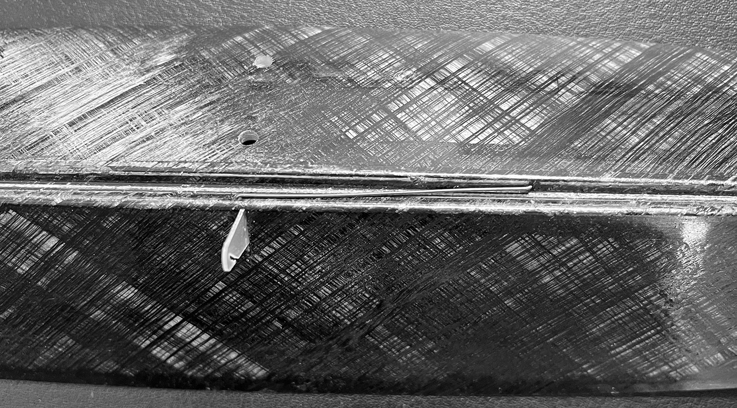
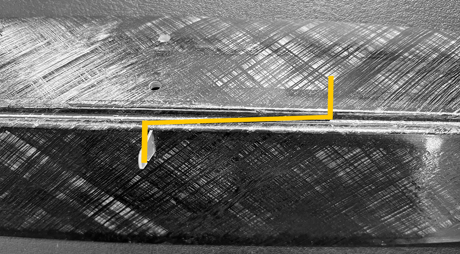
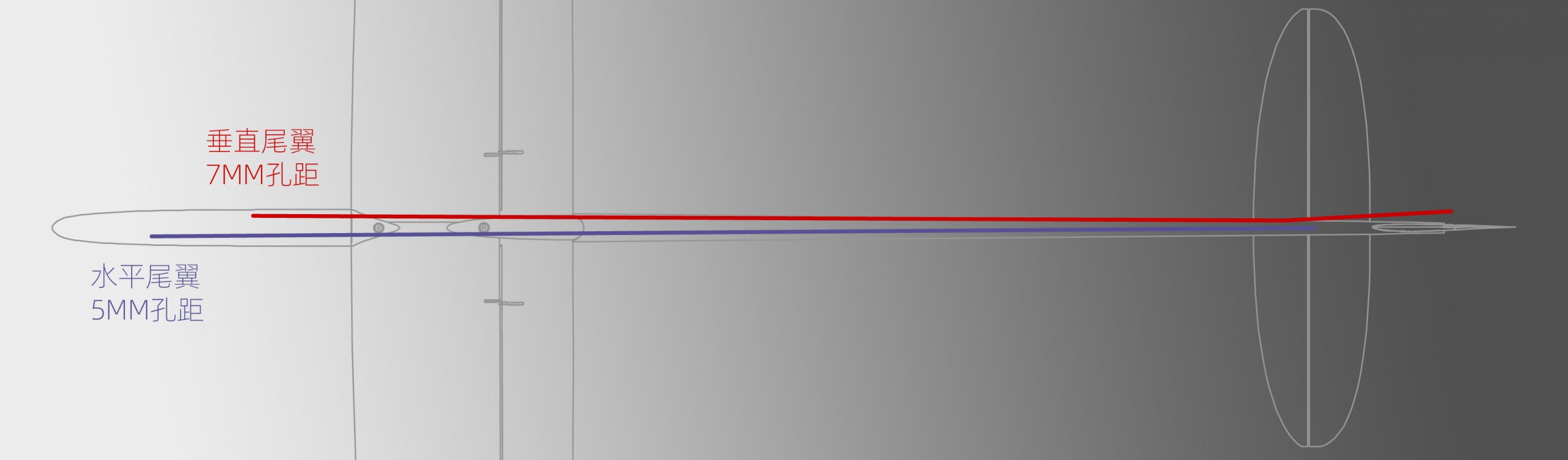
D4:确保垂直尾翼舵角
安装的位置,能够和钢丝出线孔水平,如左图;
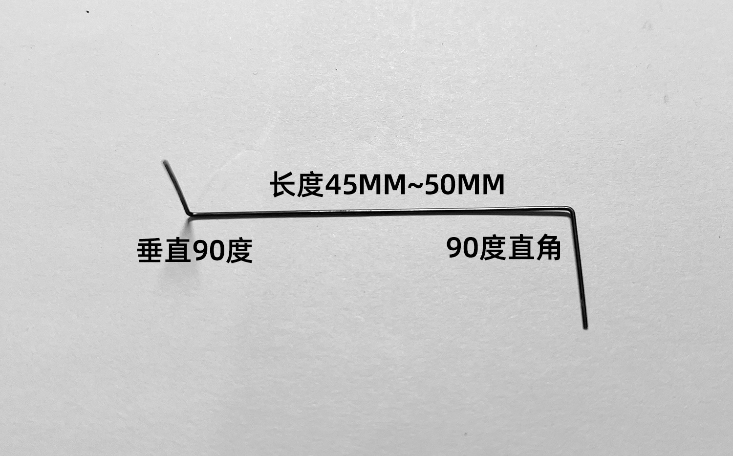
E:Bend 2 torsion springs to a Z shape respectively, and insert one to the horizontal stab and another to the vertical fin.
Step4: Fuselage Installation
Consumables needed:Masking Tape(3M2090), Epoxy Resin(E51 with medium viscosity), small disposable plastic cup, stir stick,disposable syringe and needles, disposable Nitrile gloves
Tools needed:Balance(500g, 0.1g), ruler, blades, files, dremel, drill, PE cover (not sticky), vacuum cleaner
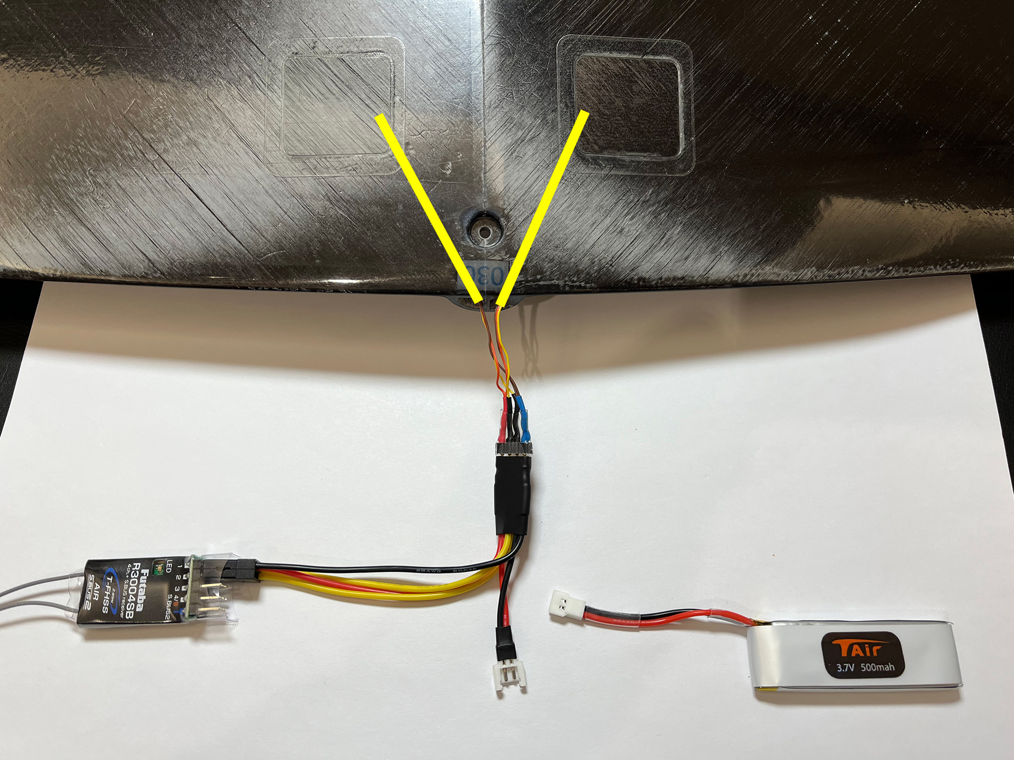
A:Cut a slot at the wing mount as shown in the figure using a dremel (to put epoxy in); cut another slot near the front of the nose as shown in the figure to lead the wires; cut the third slot to lead the antenna out.
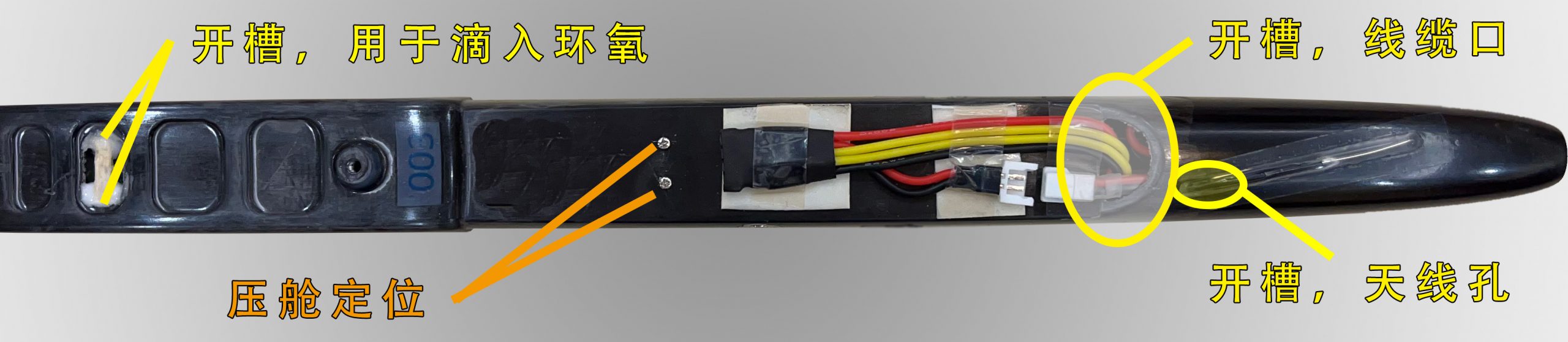
B:Insert the ballast tube, glue the front of it with CA, and drill two holes with 1mm drill for screws which will fix the ballast tube on the back
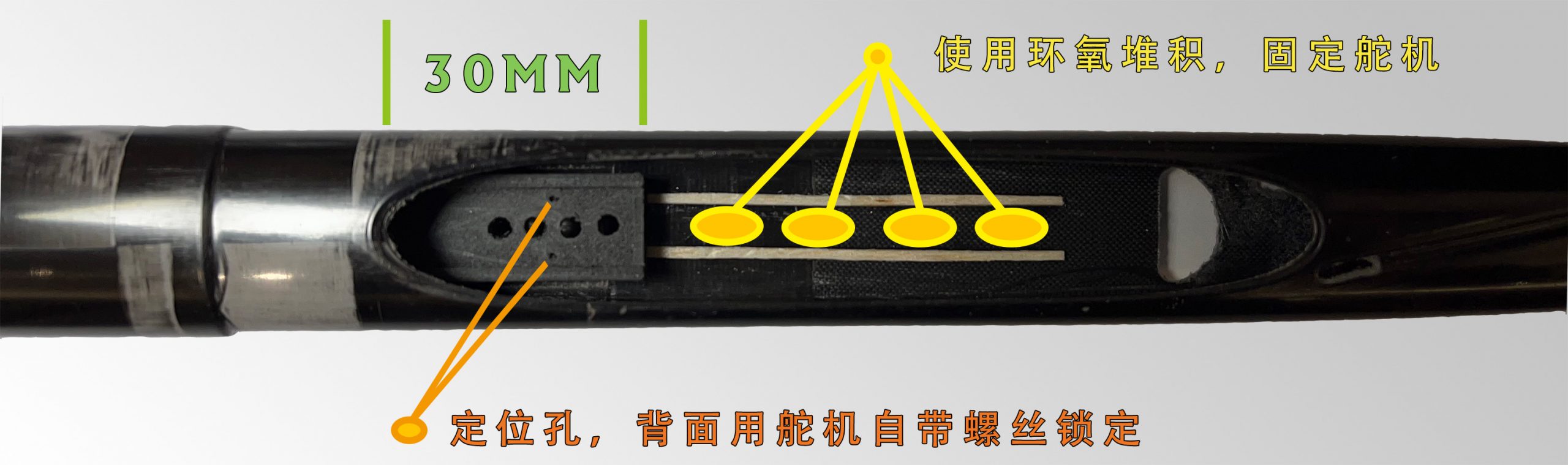
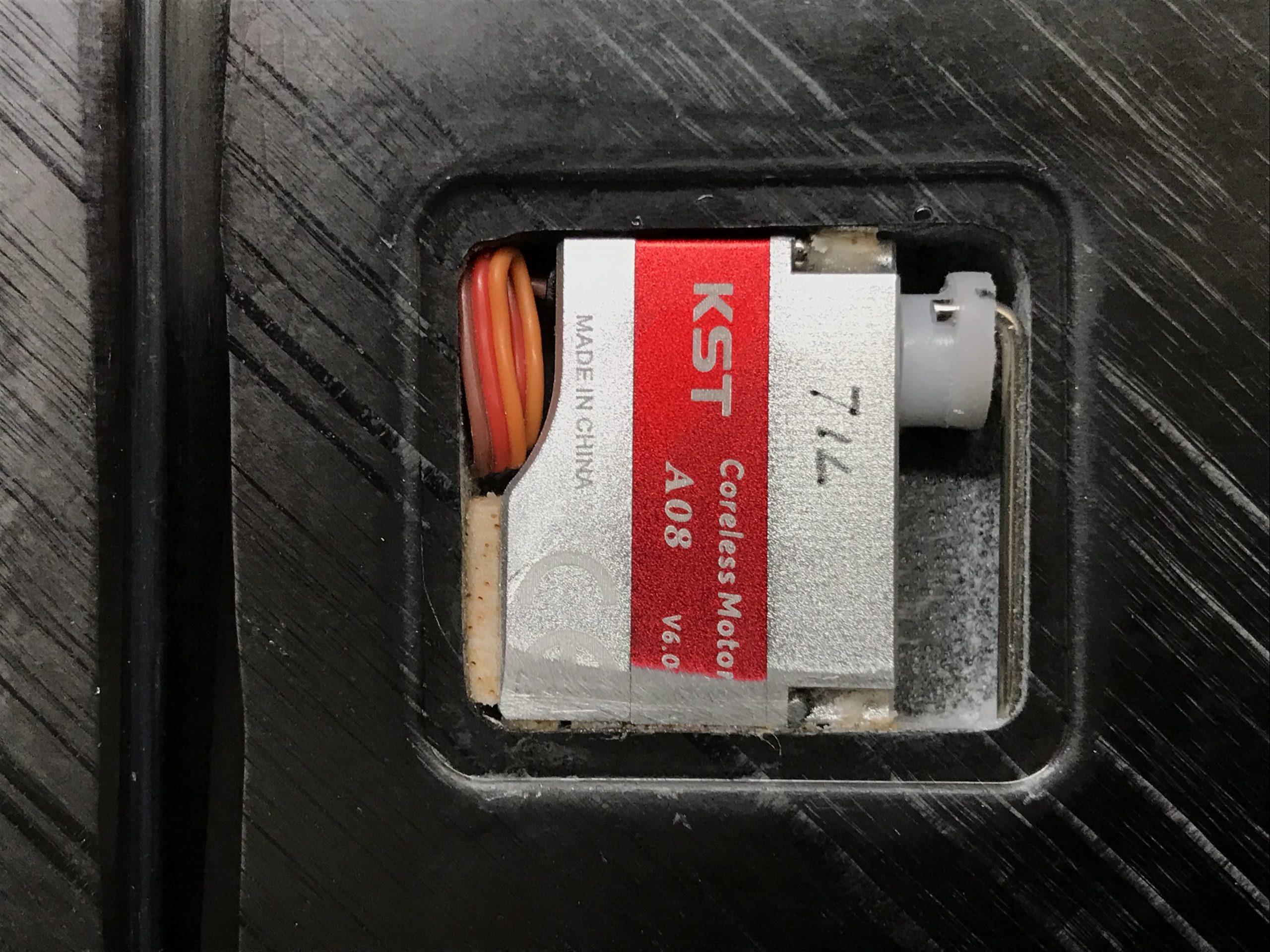
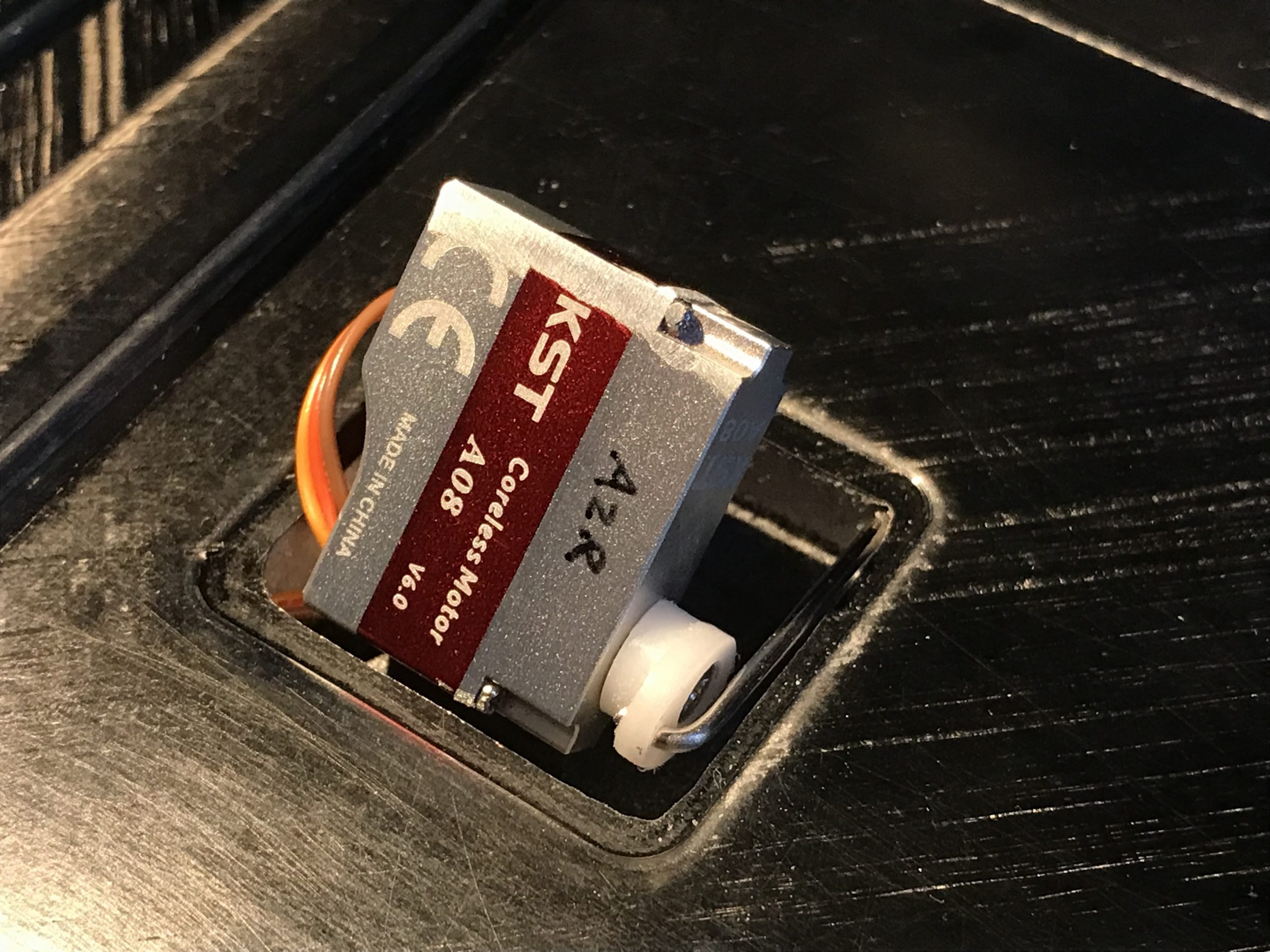
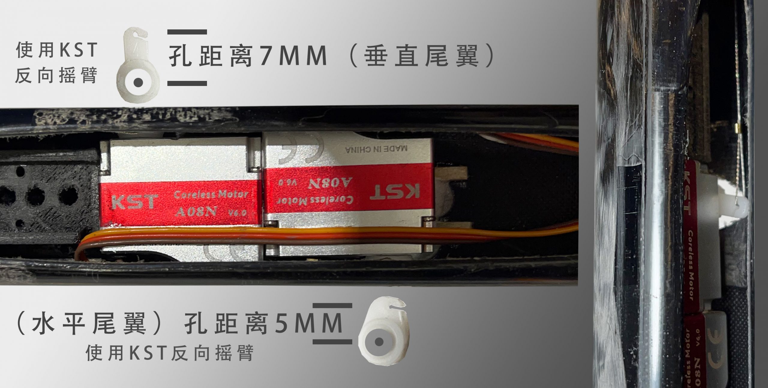
C:Install two KST-A08 or X06 (2s lipo battery recommended) to drive the tails. Since the space is tight, it is recommended to cut a slot on the side of nose right at where the arm at to screw and unscrew the arm in the future when it’s needed.
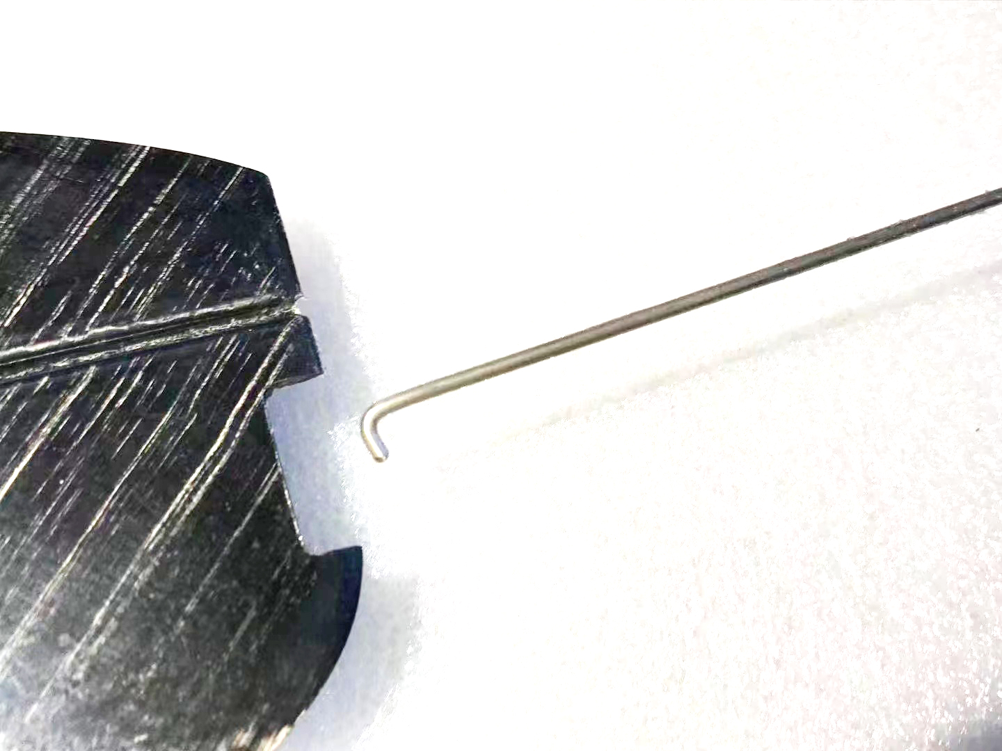
D:使用金属定位珠固定水平尾翼挂钩,并添加安装绳(运输拆下平尾后,安装绳贴在机尾旁防止钢丝逃脱)
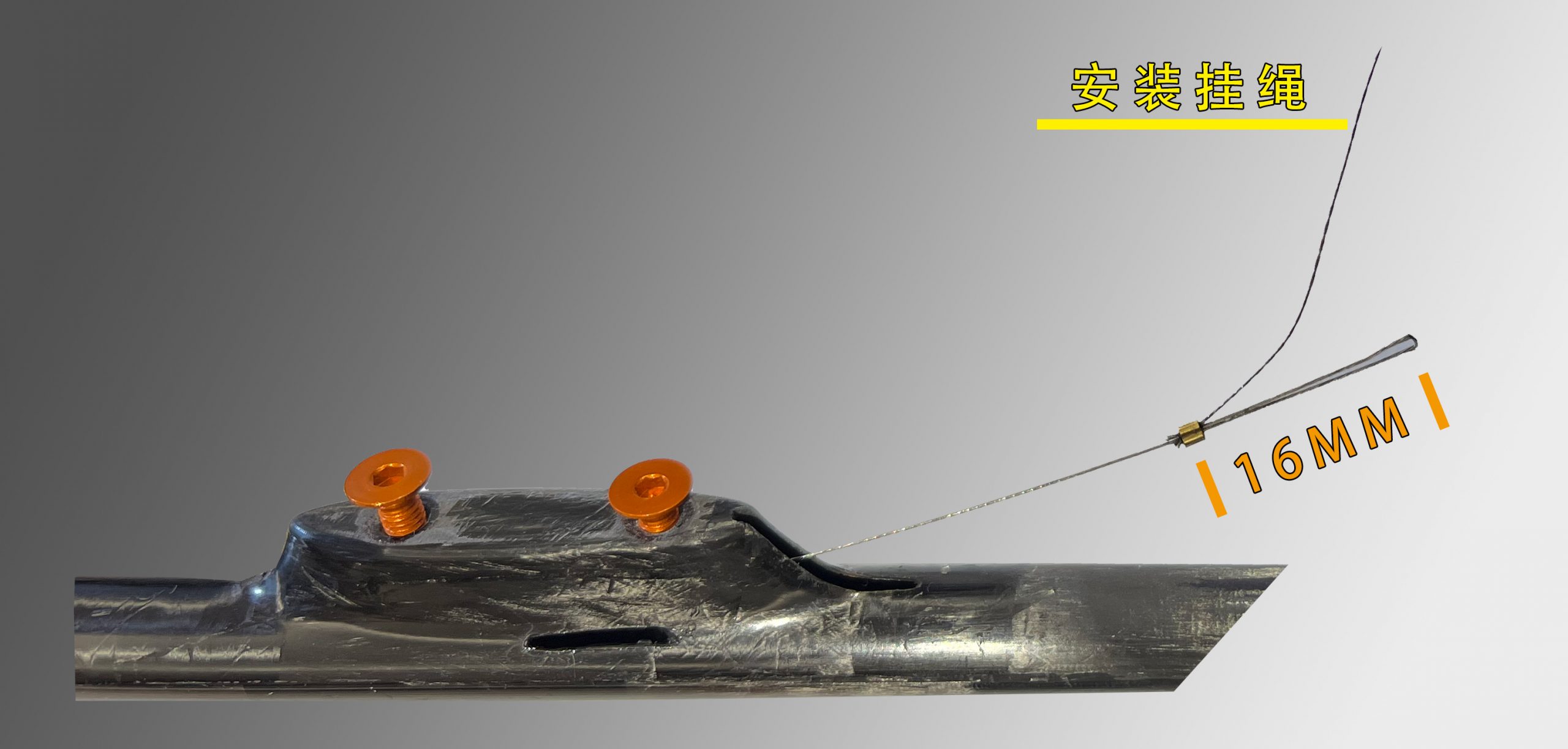
E:It is recommended to attach another short wire to help you hold and grab the control wire when you detached the horizontal stab as shown in the figure.
F:Install the control wires for elevator and rudder, respectively. Make sure two wires are not conflicting with each other inside the fuselage.
G:While installing the control wire, make sure your servo is neutral and the elevator and the rudder are at the neutral position, too. It will be helpful if you leave your radio on and keep the servos active.
Step5: Programming and testing
The Tair5 has a wide speed envelop, and the new designed airfoil will make it glide more efficiently while in fast cruise. The pilot don’t have to switch flying modes back and forth frequently. The Cruise mode is pretty versatile in different conditions. Here is the recommended settings. You can use this as your starting point.(good for intermediate pilots with less than 1000-hour stick time).
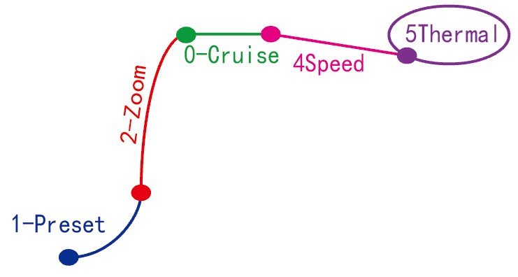
5 basic modes in total (can add more modes based on your need):
1=Preset(Rotation): The mode you use during your rotation, making the DLG climb at the right angle after you release it.
2=Zoom(Climbing mode): Minimum drag for climb.
0=Cruise(general flying mode): The most efficient flying mode for you fly around to search thermals.
3=Speed (speed mode): When you need speed to across a sink or come back from far downwind.
4=Thermal(best L/D):Use it when you are thermalling or need fly slowly
During your ratation, you should hold the preset mode. After you release the DLG, do not switch mode instantly. The DLG will nose up and start climbing. Once the DLG is heading at an ideal climbing angle, switch to Zoom mode and let it climb straight with minimum drag. When it is about to stall during its climbing, push the elevator down (up stick)to opt out and fly normally. Switch to the Cruise mode (or speed mode) and start searching for thermal.
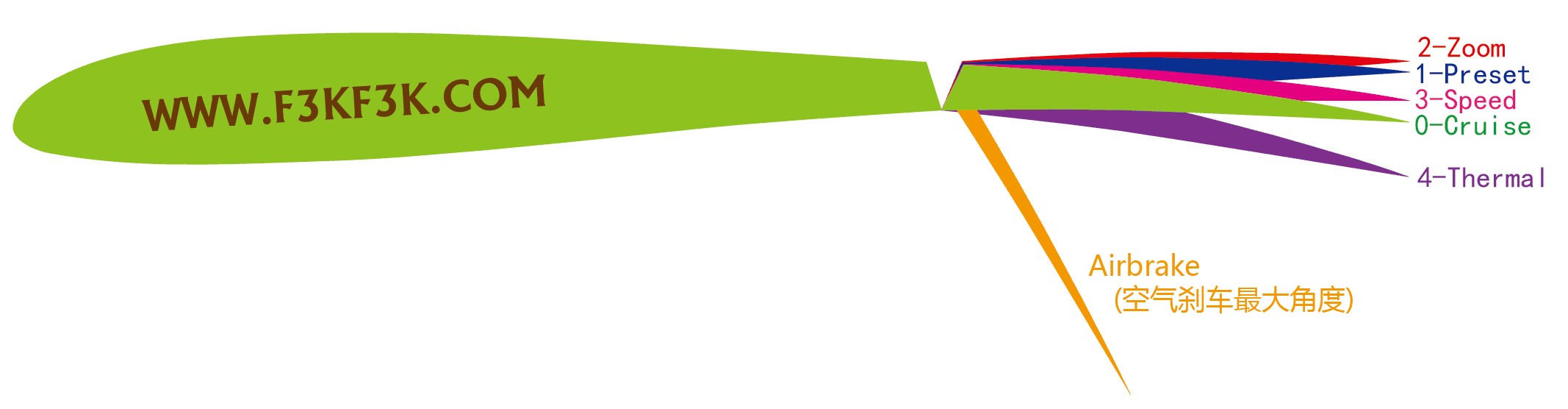
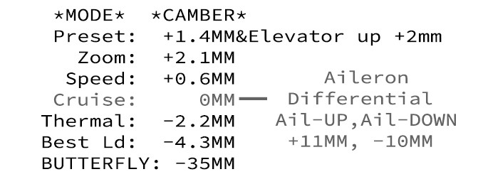
These 5 different modes have different cambers, so you’ll have to compensate it with different elevator settings:
In Preset mode, you need to have ~2mm up elevator to make the DLG nose up faster;
In Zoom mode, you probably need a little bit elevator down to keep the DLG climb straight;
In Cruise mode, all the surfaces should be at their neutral position (ideally);
In Speed mode, we’d like to have the DLG have a little bit diving tendency. Therefore, despite an up flapron camber, we can keep the elevator neutral (or close to neutral);
In Thermal mode, we need to give it a bit down elevator to compensate the nose-up caused by down aileron camber;
*In Airbrake mode, we want more than 60 degree down flapron with an appropriate amount of down elevator compensation.
Tair is sensitive to the CG.
In turbulence or strong wind CG < 75MM; Normal condition CG = 77MM; Calm CG > 78MM;
超越想象的高度 平均 65M+
新高度
TAIR5高模量超高温固化机身 祝您探索新高度!
穿透能力
TAIR5 超薄的翼型确保您在穿越下降时 不再迟延!
留空能力
极限的降阻设计结合出色的翼型 TAIR5在各种天气下拥有出色的巡航漂浮能力!